Thermal Energy Storage
Semester 2 TES can be accessed here
Thermal Energy Storage (TES) of our CSP system includes:
- Existing methods of TES
- TES structures
- Heat transfers enhancements
- Phase change materials (PCMs)
- Experiments
- Future work
- Appendix
1. Literature Review of Existing Thermal Energy Storage Method
Thermal energy storage (TES) is essential in CSP plants, enabling operation beyond periods of direct sunlight. It is widely adopted in commercial systems, with TES integrated into most parabolic trough, linear Fresnel, and power tower installations, many providing over 7 hours of storage [99]. In contrast, most parabolic dish CSP systems have not yet incorporated TES commercially [100].
TES systems can be ranked by performance, cost, and safety. Key factors include energy density, efficiency, heat losses, operating-temperature suitability, capital cost, footprint, scalability, and material or environmental safety [99]. Higher volumetric energy density generally allows more heat to be stored in less space with lower losses [100].
TES can be categorized into 3 main types: Sensible heat storage, latent heat storage, and thermochemical storage. Figure 39 show that thermochemical storage has highest volumetric energy density followed by latent heat storage and sensible storage [98],[103].
1.1. Sensible Heat System
Sensible heat storage involves storing energy by changing the temperature of a material as
Qstore = mCpΔT [104].
Sensible heat storage materials should provide high energy density, adequate thermal conductivity (>0.3 W m⁻¹ K⁻¹), and high thermal diffusivity for efficient heat transfer. They must also be low-cost, easy to manufacture, and chemically stable, with low corrosiveness and minimal environmental impact (low ODP and GWP) [105].
Below is the few best heat sensible materials for our modular small-scale CSP system based on above criterias:
From the criteria above, water is considered one of the most effective materials for heat storage in residential systems because of its high specific heat capacity and availability compared to other sensible heat storage media. The rock or pebble bed is considered another promising sensible heat storage medium, particularly because it has relatively high volume density, can operate at temperatures exceeding 100 °C, higher thermal conductivity, withstands high thermal stress, and avoids problems such as leakage or corrosion that occur with water (see Appendix). However, following our other subsections, our system operating range is first designed to work at operating temperature of less than
along with using water as HTF.
A common application of water-based TES is the solar water heating tank (Fig. 41) [106]. In direct (open-loop) systems, the solar collector heats the tank water directly, while indirect (closed-loop) systems use a separate heat-transfer fluid (HTF) and a heat exchanger to prevent contamination and enable the use of antifreeze solutions. During operation, natural thermal stratification forms due to density differences: hotter water rises to the top, cooler water settles at the bottom, and a thermocline forms between them [105]. This stratification improves TES efficiency by reducing mixing losses and enabling the delivery of higher-temperature water while maximizing effective storage capacity [106].
1.2. Thermochemical energy storage
Thermochemical energy storage systems retain heat through reversible chemical reactions or sorption processes. A general reaction can be expressed as:
Heat + C ⇌ A + B ; Q = ΔHreaction [108]
In the charging (endothermic) phase, C splits into B and A, absorbing heat Q. Thermochemical systems store energy in chemical bonds, and this energy remains stable as long as B and A stay separate. When recombined, the reverse (exothermic) reaction reforms A and releases the stored heat [109]. TCES materials exhibit the highest energy density among thermal storage methods because chemical reactions can store significantly more energy per unit mass or volume [110]. However, TCES system is not suitable for a small-scale CSP application operating at low temperature because its reaction-based mechanisms require complex reactor designs, and precise control of gas-solid or solid-solid equilibria [111].
1.3. Latent Heat Storage
Latent heat storage involves a phase change such as melting, evaporation, or crystallization at a constant temperature. Because of the high enthalpy associated with phase transitions, latent TES stores more energy than sensible heat systems of the same size, though it operates over a narrow temperature range [113]. The stored energy is given by Qfusion = mL. Solar thermal energy can be effectively stored as latent heat through the use of phase change materials (PCMs). These materials provide higher energy storage capacity per unit mass or volume [107].
PCMs are generally classified into three main categories [107]:
- Inorganic PCMs, such as hydrated salt solutions composed of natural salts and water
- Bio-based PCMs, derived from natural fatty acids like vegetable oils
- Organic PCMs, typically made from petroleum-based byproducts
2. Thermal Energy Storage Structures
Thermal Energy Storage (TES) stores heat using suitable thermal materials. Our overall proposed design is a water tank packed with encapsulated PCMs, as shown in Figure 44, which is integrated with other CSP subsystems in Figure 45.
The key TES design specifications are summarised below. In the proposed system, available installable volume is prioritised over container geometry, allowing greater flexibility in the final configuration. The following sections outline the rationale for these specifications and describe how the TES design will be implemented in the next semester.
2.1. Selection of TES systems
Among the TES existing options, a water tank with encapsulated PCMs offers the best fit due to its compatibility, availability, and low cost to our modular CSP.
2.2 Existing TES structures
For the chosen TES system, two configurations are possible depending on how the PCM is arranged: compact and encapsulated. Compact systems hold the PCM in a single large vessel with an internal heat exchanger, typical of water-heating applications [115]. Encapsulated systems use many small sealed PCM units immersed in the heat-transfer fluid, offering greater design flexibility and compatibility with both air and water heating networks [115],[117].
Table 38 illustrates why the encapsulated PCM system is preferred, as it offers leak-proof containment and enables more efficient charging and discharging
3. Heat Transfer Enhancement
3.1. Exisiting Methods
For PCM systems, heat transfer is commonly improved through encapsulation, metal foams, and conductive meshes. Encapsulation increases the surface-area-to-volume ratio, enabling faster melting and solidification while preventing leakage [115]. Metal foams create a highly conductive porous network that spreads heat rapidly through the PCM and reduces supercooling [119]. Conductive meshes offer a practical middle ground, improving thermal diffusivity at lower cost than full metal-foam structures (see Appendix). In addition, metal-encapsulated containers are often selected to further maximise heat transfer, as discussed in the next section.
4. Phase Change Material (PCMs)
4.1. Material Selection
To match with our CSP system, several phase change materials are selected based through material scoring as shown (see Appendix for selected PCMs propertises). Among them, paraffin is chosen as primary PCMs due to its low-cost, safe, and high latent heat enthalpy.
4.2. PCM Container Selection
A variety of PCM containers shown in Figure are commercially available, but these options differ in thermal performance, cost and mechanical strength. Metal capsules (aluminium or stainless steel) offer high thermal conductivity for faster charging and discharging, while plastic-based containers are cheaper but less effective for heat transfer [117].Among all options, the aluminium bottle is selected based on the criteria shown in Table 40. However, the stainless-steel cylinder remains a promising alternative for next semester designs, offering smaller size, better heat diffusivity, and moderate cost
The specifications of the aluminium bottle used to contain the PCM are tabulated below.
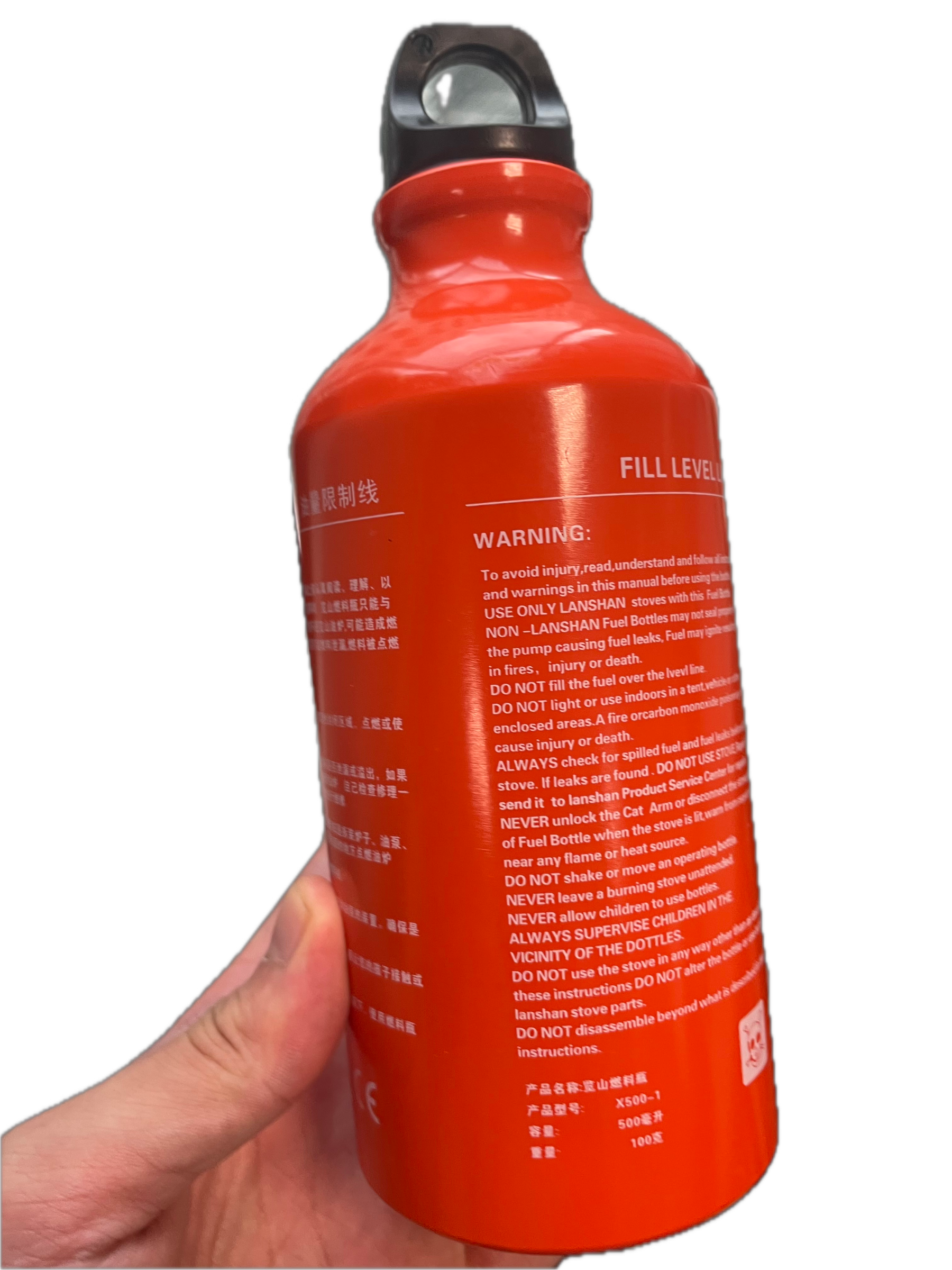
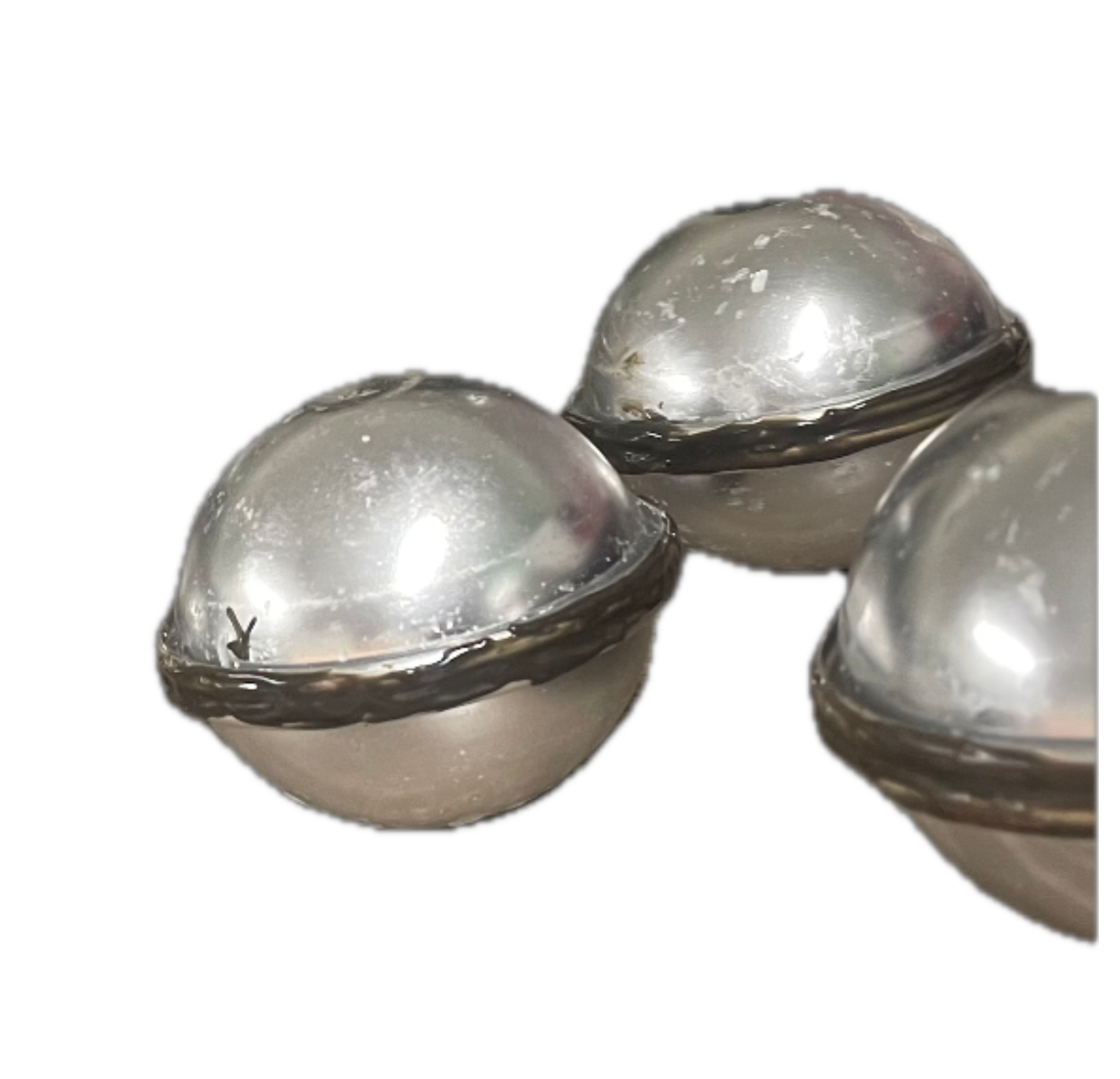
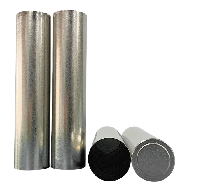
Figure 48: Aluminum bottle; Ball Capsules; Steel Cylinder
5. Proof of concept:
5.1. Experiment 1:
The temperature decreases very quickly at the start, then the curve bends and the cooling slows down near ≈59 °C. The shoulder around 59 °C corresponds to the solidification of paraffin wax: latent heat is being released, so the temperature falls more slowly than in purely sensible cooling. Being a mixture of many hydrocarbons, it solidifies over a temperature range (~55–60 °C) [121].
5.2. Experiment 2:
Results and Analysis:
Both graphs show that under moderate insulation, adding paraffin wax significantly slows the cooling rate compared to the control box with only water. In the 150 mL paraffin test, the water remains above 50 °C for an additional 0.9 h (5.5 h − 4.6 h), while in the 500 mL test, the retention time at 50 °C increases to 2.8 h. Scaling this trend to our full TES volume suggests a retention time of more than 5 h at 50 °C and up to 9.5 h at 40 °C with the same insulation. This confirm paraffin wax increases thermal storage capacity and slows temperature decay due to its latent heat and heat capacity. Larger PCM volumes provide proportionally longer retention, demonstrating strong potential for sustained heat delivery in the final TES design.
5.3. Experiment 3:
The cooling curves show that the paraffin box maintains higher temperatures for a longer period than the water-only box under identical insulation. At 40 °C, the paraffin box reaches this point at 11.3 h, compared to 8.6 h for the non-paraffin box, giving an additional 2.7 h of useful heat retention. This extended duration is due to the latent heat released during paraffin solidification, which slows the temperature drop after melting. These results indicate that when scaled to a TES unit with similar installable volume, PCM integration will provide longer temperature retention than water alone, improving the system’s ability to deliver sustained low-temperature heat.
6. Future work
7. Appendix C